| Finally, an FM Antenna that is really worthy of our babies! |
C Crane Company APS-13 Page at C Crane APS-13 Page at Manufacturer's Page |
|
Over on the immediate right at the bottom is the antenna that I keep on the Marantz
system currently in my office. The picture at the right shows reception on a 2285b receiver; now I use a 2130 tuner,
which is about 16% more sensitive, with a Magnum Dynalabs Signal Sleuth RF
preamplifier to "front-end" the whole thing. A world of difference.
The 2130 has "that sound", but the RF front end technology is getting
a little old in the tooth... the Signal Sleuth really makes a difference in
what it can hear (and I know the 2130 is operating perfectly!)
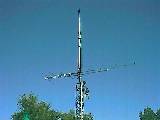
The antenna is an APS-14 (they now sell an APS-13) It is a large, 14-element,
dual-driven director-only design that pulls in KMHK, a classic rock station 179 air
miles (see map here) away in Hardin, Montana fairly
reliably, as you can see at the right top. That's a full quieting signal about 99% of
the time. Afternoons, skip does tend to come in and whack KMHK upside the head, but
that's actually kind of fun.
I live on the plains, so terrain conditions for this kind of distant station
reception are just about ideal, but the point is that at 179 miles, you
need a pretty amazing antenna to pull a microvolt or two into your FM front end!
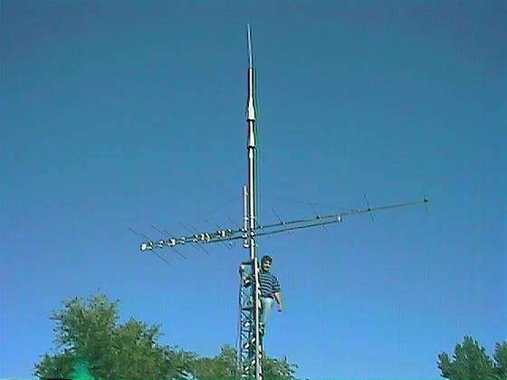
If you click on the thumbnail on the bottom, you can see a 4x version of the antenna
image. That's my friend Mike on the tower below the antenna. He's six foot even so that
should give you an idea of the scale of the antenna against the tower, etc.
The tall pointy antenna above the APS-14 is an AEA "Isopole", a 144-MHz
design that is omnidirectional and listens at the horizon level. I use it to catch DX
conditions on FM, though it's detuned at 88-108 MHz, it still does a very credible job
on the FM broadcast band. |
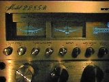
179 Mile DX Quality
On Marantz 2285-B
(45% scale, in stereo)
APS-14
(click for larger image)
|
|
| General Electronic Restoration Tips |
N/a |
Our Technics gear has, in general, withstood the test of time quite
well. However, time has, and is, modifying these units every day,
and they move further away from the original design specifications
as a result. What can we do? Should we do anything?
I think we should. And we can. My aim here is to provide some general
tips that are aimed at electronics types. If you're not technically
sophisticated, just skip this tip - you don't want to electrocute
yourself, or ruin your prized Technics.
- Carbon Resistors: These components age rather quickly compared to
most other components. As they age, two things happen. First, they
change in value. That doesn't have to be a critical problem; A
good design will put a value in there that based on the rated
tolerance of the resistor itself lands dead-center in the middle of
the needed value, and so there is some room for change. I think we
can be confident that Technics got this right very consistently
based on the observed performance of the units. Still, you should
be aware of it. The second thing is that they actually get noisy.
That's right - they generate noise! For this reason alone,
it's a good idea to replace them if they are found in low level
signal circuits, either audio or RF. Choose the replacement carefully.
For audio circuits, high precision metal film resistors are great.
For RF, they're terrible. This is because of the RF signal characteristic
known as "skin effect". RF tends to flow on the surface of
a conductor, rather than inside it. So the film resistors turn into
odd-value components that also, unintentionally, contribute inductive
and capacitive components to the circuit. Find a resistor type that
meets the design limits - value, tolerance - that is designed for
RF-neutral operation. Consult your parts manufacturer. I cannot overemphasize
this issue - never use a metal film resistor in an RF signal
path of any type.
- Electrolytic Filter Capacitors: These, along with carbon resistors, are
the components that change the most and have the most deleterious effect(s)
on the sound and performance of older audio gear. Factors that affect these
parts include age, frequency of use, heat, and signal characteristics. Things
that change include the actual capacitance, the internal resistance, the apparent
inductance of the part, the breakdown voltage and the leakage. In short,
basically everything changes, and rarely for the better. The electrolytic's
dielectric can dry out, and that leads to all manner of bad things. Eventually,
they will either fade away in capacitance, open, or short out, this last
behavior often causing circuit damage. So these are prime candidates for
a replacement program. When you replace an electrolytic, use the same value
in microfarads. Resist the temptation to increase the value of filter
capacitors, for instance. Why? The general answer is that the designer(s)
knew what they were doing - they didn't just "put" those values there,
they designed them in for one or more reasons, and in the case of Technics
designs, cost was usually not the key factor. A more specific answer is as follows:
If, for instance, you put in larger capacitance value power supply filter
capacitors, the cold-start inrush current into the caps, and thru the rectifiers
can be significantly greater than the rectifiers - and perhaps the power
transformer also - were ever designed to handle. If a rectifier blows, you can cook
off a lot of the rest of the unit... and you don't want that, right? In signal
circuitry, the electrolytics perform more than signal transmission functions, they
also are part of the inter-circuit impedances, and those can affect frequency
response and phase shift, both of which can produce immediate (and annoying!)
changes in the unit's ability to handle audio. Back to replacement specs; specify
the same, or higher, voltage rating on the electrolytic. Use polarized parts where
polarized parts were used (probably everywhere... otherwise use nonpolarized high
quality caps, of course). Don't replace nonpolarized with polarized, ever
and don't replace polarized with nonpolarized even if it seems like nothing could
ever happen as a result - it can, trust me on this. Nonpolarized electrolytic caps
tend to die if they are kept polarized one way for long periods of time. I don't
know why, but I do know this to be a fact from long personal experience in
repair and design.
- Potentiometers, Switches and Buttons: These get noisy because they are simply
accumulating dirt and/or corrosion. When they are on one position, the surface of
the contact for the open circuit or part of the path of the pot's wiper is
uncovered, and it picks up debris and/or corrodes. The best cure, hands down, is a
good "tuner cleaner" product. I know people who spray 3&1 oil on pots
and switches. It works, but it can be messy initially, and because the lubricant
leaves a tacky film, it forms the basis for future debris accumulation problems. Of
course, oil being what it is, spraying again with 3&1 again fixes the problem
completely for a while, and if that makes you happy... hey, do it. :-) But a nice
tuner cleaner with a built in dry lubricant (like that blue stuff I can't remember
the name of right now) works as well, and for longer. After applying, run pots
through their full range at least ten times, perhaps more. Work switches in
and out. Do all of this with the power off - it won't help to have it on, and
in some cases might hurt. Speaking of power, the power switches and speaker
switches are problem areas. They corrode like everything else, but because they
handle so much power - high voltage and some significant current in some cases as
well - they're a bit tricky to clean up. Sometimes it takes a few tries, and
sometimes you simply have to maintain them at a higher rate than anything else in
the unit.
- Plugs, Sockets and Relays: Just like switches, plugs and sockets accumulate
corrosion and debris. Pull them, douse both the male and female ends carefully with
the tuner cleaner (or 3&1) and then plug them into, and pull them off of, each
other at least ten times. This "wipes" the surfaces against each other,
helping to remove corrosion. The oil is a good deal in this case, because since the
connectors don't have to move, unlike a switch, the oil will just sit there. It
seals the surface, reduces future corrosion, and generally helps and does not
hinder. This is also true of external plugs, such as RCA jacks. Don't use oil or
tuner cleaner on relays. Relays need to be "dry" - the only good
relay is a dry relay. File your relays using the finest file you can locate, and we
are talking very fine here. This is true of any relay, but in the case of
our classic amps and receivers, these speaker protection relay connections carry a
lot of current and anything other than contact to contact connections will
age the contact faster than it would otherwise normally age, leading to more
problems.
--Ben
|
| Replacing the small bulbs (stereo, Dolby, dial pointer, etc) |
n/a |
Often, it is difficult to obtain correct replacements for the
smaller incandescent bulbs used in older Technics units. This tip
describes an way around the problem for bulbs that match physically
but not electrically.
Something you can do to replace the smaller bulbs is series a couple
of bulbs that aren't the right amperage, but the right physical
configuration. For instance, if you have trouble getting the right
bulb for the dial pointer because of current (ma) requirements, you
can often take two higher current bulbs that are physically correct,
and series them, mounting one in the designed location, and the other
somewhere handy inside the chassis where it won't show. The trick is
to make sure that the resulting current requirement is less
than that of the factory-specified bulb.
As an initial rule of thumb, if you series two bulbs, the bulbs will
probably draw less than 1/2 of the rated operating
current; if you series three, less than 1/3rd, and so on. This is
generally true when the sum of the lamp voltage ratings is higher than
that of the applied voltage across the whole series string. Even when
that is true, because the resistance of a hot filament is nonlinear
and varies with the design of the filament, you must measure
the current drawn by the series string and actually verify
that it is under the rating for the Technics unit. In at least one case -
stereo indicators - setting up a situation where the current draw is
more than the rated amount will cause damage to the receiver
(destruction of the stereo decoder IC in this specific case.) So
measure!
For example, recently I replaced a stereo indicator that was supposed
to be 30 ma/12v with a series of two 8v/40ma bulbs. The sum of the
rated voltages is 16v, so my rule of thumb that says the current
draw would be 1/2 or less than the rating (40 ma) comes into play.
I put one on the indicator, and the other I mounted behind the
indicator panel, inside the chassis. When I measured them, the
current draw at 12v was only 16 ma, the bulb was more than bright
enough, *and* the voltage across each bulb was only 6v, so they'll
likely last much longer than they would if used in "normal"
8v service. As a side benefit, the load on the stereo IC's lamp
driver circuit was decreased from 30 ma to 18 ma, and that IC is now
likely to last longer as well.
|
| Rock EQ with Separates |
n/a |
Rock music fan? Me too. You know what the "Loudness" contour does?
It kicks up the amplitude of the low bass and higher treble signal
components when the level of the music is low. The idea is to
increase the levels just enough to match the amount that your ears
lose sensitivity to those tones as the overall level of the music
drops. So, as you turn the music down, the parts you would normally
begin to lose track of remain perceptible to you. Which is fine.
Preamps are designed to apply more and more
loudness contour as you turn the volume down, or less and less
as you turn it up, however you want to think of it.
If you're like most modern rockers, you're likely to be a fan of
significantly enhanced bass. Bass is a big part of modern music.
And bass from Technics gear is heavenly!
Well, if you have a separate amplifier and preamplifier, and the
amplifier has its own gain controls (like the 170dc, 300dc and
so on,) then here's what to do:
- Turn the amp gain controls all the way up and leave them there.
- If you have control of the source volume - E.G., tape deck settings - then
turn that up as far as possible without distortion.
- Finally, control the volume exclusively from the preamp.
Here's why: The loudness setting on the preamp has less and less
effect as you turn the preamp's gain up. So, with the amp turned up, and
possibly the source signal turned up as well, you don't need to advance
the preamp gain that far to get a high output. And, with the
preamp gain setting lower, the loudness contour is further engaged,
hence stronger bass (and treble) enhancement. Of course, you can
push this even further with the bass equalization controls on the
preamp.
And conversely, if you think the loudness on your preamp is a little
too much, turn down the gain on the power amp, and turn up the
gain on the preamp further. It'll significantly reduce the amount
of loudness compensation that the preamp applies, great for classical
music or any situation where you want to hear the music closer to how it was
mixed to the recording (which I note wryly is very seldom what the
original artist had in mind, but does usually reflect the producer and/or
engineer's vision of the final product...)
Enjoy!
--Ben
|
